

Banjo
-
Posts
1885 -
Joined
-
Last visited
-
Days Won
95
Content Type
Profiles
Forums
Events
Gallery
Blogs
Everything posted by Banjo
-
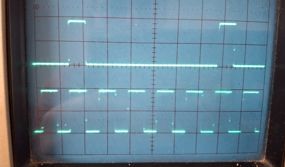
I've had some success, in the next stage of the development of a Trigger Wheel, & CAS signal, from within a K Series dissy. The Bosch K Series dissy was used, because they are physically larger in diameter, than the more common K series dissy body. The rings of rare earth magnets worked, but did present some issues. There are a couple of incremental rotary encoders used in industry; & the education industry, that provide an identical output to the rare earth magnets & Hall Sensors, but are a "drop in" item. Rotary encoders, can provide outputs, that can be used to indicate the rotational speed of the encoder; the direction of travel of the encoder; & the actual angular position, at any time. An industrial grade absolute encoder, can be quite expensived, but the small "educational" incremental ones, for teaching concepts; are less than $ 30.00 ea. As can be seen in the three pics below; they are relatively easy to mount, in the dissy. If You want to read more about encoders, in general, then head across to this link. https://en.wikipedia.org/wiki/Rotary_encoder These encoders come in a variety of models, with different numbers of pulses per single rotation. Because we are interested in angular movement of the distributor, & everything ECU wise is related to degrees BTDC etc.; I chose, & ordered; an encoder that provided 360 pulses per rotation. The encoder has two of these outputs, slightly off-set angularly, so that it is possible to work out which direction, the encoder is rotating in; although that is of no interest to us, in this dissy application, as the dissy only rotates in a clockwise direction. (more on that second output later) However, most ECUs accept pulse trains from trigger wheels, that produce pulses of 24/36/60/72 pulses per single rotation, of the crankshaft. As the dissy only rotates once per two (2) revolutions of the crankshaft, then we are only interested using 180 of those dissy encoder pulses, & we set the ECU up, as if these pulses are being derived, from the crankshaft. I then decided to see if I could divide the 180 pulses per "effective crankshaft revolution", down to one of these above common ECU trigger wheel numbers, for a crank shaft rotation. Pulse chains in electronics, can only be easily divided by whole numbers. 180 divided by those trigger wheel numbers are (180/24 = 7.5; 180/36 = 5; 180/60 = 3; & 180/72 = 2.5; 180/4 = 45. We can only easily divide by whole numbers in electrionics, so dividing the pulse train by 3 or 5 produced the equivalent of a 60 or 36 tooth crank trigger wheel. Most ECU manufacturers, advise that crankshaft trigger wheels between 24 to 60 teeth, provide best resolution. So it didn't take long to then produce these switchable trigger outputs, to an ECU. Oscilloscope grabs of the primary (360) & divided by 3 & 5 pulses, are below. I had left my single CAS magnet & Hall Effect sensor in the base of the dissy body, so do have a working system. However, the rotational encoder sits up pretty high, so I cannot create my low profile dissy, with my "jam jar" lid. Could I possibly, use that second pulse chain of the encoder, to produce a single CAS signal ? Unfortunately; not with this particular encoder, but could be possible with a absolute positional encoder, where each of the 360 pulses per rotation, creates a unique number. We could only look for just one number, & use that pulse as the CAS pulse. However, it may be simpler than that, as an absolute rotary encoder has a single pulse per revolution, that resets the counters. That may make a perfect CAS signal, if brought to the outside of the encoder. All I've got to do, is find an "absolute" rotary encoder, in a small footprint, at a reasonable price. Simon down in Tassie, is sending me up a K Series Bosch dissy, so I can then try this theory out, in practice. It may be; that ultimately, we may be able to even accomodate this angular encoder, into one of the "narrower", olde K Series dissies. All good fun ! Cheers Banjo


-
Hi John, Just looking at those marvellous photos again, I think I spotted a silver "Shilling", sticking out from underneath the drivers seat, that may defray the resto costs a little. Then, again I might be wrong. . . . . . . . . It may well turn out to be a "sixpence piece"; . . . . . . . or; just a washer ! Cheers Banjo
-
Hi John, Welcome aboard ! Thanks so much for this post, & all the pictures. Excellent story. Truly amazing ! So whereabouts is this relic from the "Toyota past" residing ? I see it is RH drive, so my guess is in rural Australia, or New Zealand. I note it has a push button radio. Wouldn't it be great if it still worked ? It's a great shame, the meeting of "Mazda & Toyota" on the passenger side front area. Because they are so simple, it won't be that hard to get it going again. The big question, will be how many $$$$$$ are needed to get that body rigid again. It's the inside bits in channels etc, where You can't see; that will be the real places, which will be crucial whether it can be restored. I'd be placing it on a concrete garage floor, & removing the wheels, one at a time; & jacking up that corner with a jack, & see what the body's creaks & groans tell you. Nothing is really not doable; but at what cost ? You are lucky though; that all the glass is there. Even your sister's attack on the front guard, could probably be returned with a good metal worker. Would love to hear what the next chapter will be for your "family treasure" ? Cheers Banjo
-
The Cherry ZF sensor You have purchased, is one of the best available, & usually very expensive here in Australia. It does not however, come with a built-in LED to indicate it is working & producing an output, when You place the sensing face close to a ferrous metal object like your vertical pin. They are generally utilised to sense ferrous teeth on a trigger disk, as depicted on the spec sheet. As your ferrous pin, has a curved surface facing the sensing surface of the Hall Sensor, it may well need to be a bit closer to the pin, than the 1.5mm, the spec sheet indicates for the gap. The only way, is to test it. As the Cherry unit does not have a built-in LED, You are going to have to hook up an external one, across the output of the Cheery Hall Sensor, as per my sketch below. You will need a small 6 or 12 volt battery to power it. The frequecy response of the Cherry Hall Sensor of 15kHz, makes it idea for this application. Most commonly, these sensors are used to pick up ferrous 30-60 teeth on a trigger wheel, attached to the crankshaft pulley. However, in an application like distributor body, where the distributor rotates at half the speed of the crank; & only has one tooth per rotation to sense, it is more than suitable for your application. So get yourself an automotive LED bezel lamp, suitable for 12 volts, at an auto store. These will already have a resistor, inside the lamp, in series with the LED, as the LED only needs 2-3 volts across it; (depending what colour they are), to light up. Detach the Hall Sensor from the dissy body, & then place various sized bolt heads, washers etc., close to the sensing face, & get a feel for how close it has to be, before the lamp is turned on fully. Then put it back into the dissy, & move it as close as necessary, to get the LED light to come on reliably & consistently. Let us know how You go. Cheers Banjo


-
Couple of questions ! What is the model number of the Hall Sensor You are using ? Is it a model that detects north or south poles of magnets; or is it one that detects ferrous metal targets ? Does the Hall Effect sensor have an LED light, built into the rear, where the cable enters the Hall Sensor. The setup You have there, maybe permanently switched on, depending on how sensitive the Hall Sensor is, & whether the "steel base", from which the pin protrudes is too close to the sensor, whilst it rotates. Nomally, You connect the DC supply voltage across the twi wires, that supply the Hall Sensor, with a DC voltage between 5-12V DC. Then rotate the dissy, & see whether the LED turns on & off, when the vertical pin passes the sensing face of the Hall Sensor. If You have model number for the Hall sensor, then list it here, & I can look it up, & see what type it is. Be careful when connection it up; as some Hall Effect sensor colour codes are a bit unusual. I've got some here, where the "brown" wire is +12Vdc, "black", is the output wire; & blue is the -ve wire. Cheers Banjo
-
Good to hear, You've got lots of things "wished for", done to Your ride, & it's working well, & keeping a smile on your face. I'm not on any social media sites, exept this RollaClub fratermity. You can always use the Private Messaging, (PMs) up in the top right hand corner, if You simply want to confer in private. You will always receive an email, advising that there is a message there for You. I'll also send this message to You, via a PM, so You can see how it works. Cheers Banjo
-
This is a complex subject, as much of the changes to be made, are a conditional, on what You want to achieve. Here is a link that will take You to a wealth of subject matter, on the web, regarding this subject. Google Search Listings Click on videos, as they are more dynamic, in terms of understanding this subject. For instant; the first video, is intersting material; but is really only for those in motor sport, who are into drift racing. The whole McPherson strut system, is a bit of a compromise, in many ways, as the top pivot point does not move dynamically, as the suspension goes up & down, as did the older double wishbone type, of front suspension. The other point, is that not all the McPherson front struts, used in early Toyotas, had the same KPI (king Pin Inclination) angle, as Altezzaclub, has mentioned. I know, as I spent several frustrating weekends, learning about this, when I originally fitted Celica RA65 struts to a KE-30, with Corona lower control arms. https://www.rollaclub.com/board/topic/63524-ke-3055-brake-upgrade/#comment-636927 Cheers Banjo
-
These ones claim +/- 1.5 deg adjustment. Front Toyota Camber Adjustment Bolts
-
Hi, Good to see You on here again. How's that 4K engine going ? Did You eventually find your fuel pump problem, & fix it, or fit a new one ? The best fix for your negative camber issue, is to put adjustable camber top plates, to anchor the strut top bearing assembly. T3 has what You need . . . . https://technotoytuning.com/toyota/ke30 I've had mine for years & years, & once I got it set up, with a small amount, of positive camber, I've never touched it since. The additional way to add more negative camber, is to fit longer lower control arms, although you'd be lucky to find them, these days; off early Coronas & Celicas. Cheers Banjo

-

4ku/5k head (Twin row timing chain not lining up)
Banjo replied to Thomasdillon's topic in KExx Corolla Discussion
Our Pleasure ! Just make sure everything lines up, as per my pic below. The keyway on the crankshaft sprocket, must be facing perfectly vertical (in line with the bores of the cylinders; when You fit the chain. I noticed in your photo, it was at about 11:00 o'clock. This is particularly important, when carrying out a timing chain changeover, with the engine in the car, as they normally are tilted slightly, to wards the manifolds, side of the engine. Good Luck, & let us know how You go. Cheers Bango
-
4ku/5k head (Twin row timing chain not lining up)
Banjo replied to Thomasdillon's topic in KExx Corolla Discussion
Hi Thomas, There are a number of threads on this site, about installing the timing chain, & associated pullies on the K Series engine. Here a link, to one I did about 10 years ago. https://www.rollaclub.com/board/topic/71502-fitting-k-series-camshaft-timing-chain/#comment-696083 Frankly, the very small amount the hole position in the camshaft sprocket is out, is not going to create any issues at all; & You will not notice, any difference, in performance, unless the engine was highly modified, which it appears, not to be. Good question, but just put it back together as is, & You won't have any issue, or worries at all. Cheers Banjo -
ZRE152R - 2010 Corolla sedan boot lid
Banjo replied to SilvaRolla's topic in ZZExxx/ZRExxx Corolla Discussion
Hi Paul, I didn't know but a quick search of Google, which now uses AI to help You out, did find a number of sites, which referenced the answer to this question. Here is an Australian site, that advertises these boot lids, & advises that all boot lids for 2010 - 2013 models were the same. https://www.myautoparts.com.au/products/genuine-boot-lid-suits-toyota-corolla-zre152r-zre153r-2010-to-2013?srsltid=AfmBOooY2zlGzTYVe7BksIVWefB6RUadx2f24Lo_bAyaeLDSK8e3juyb Hope that helps ! Cheers Banjo -
There is nothing more stable, in terms of an electronic ignition system, triggering system; than a "crankshaft mounted", iron toothed, or "flying magnet", trigger wheel. Stable, because there is no need, at all for a C.A.S. (Camshaft Angle Sensor), if You use a trigger wheel with a missing tooth, & run the ECU in a "Wasted Spark" ignition only, or EFI Ign & Inj mode.There is plenty of room usually, down on the crankshaft pulley, to mount quite large diameter wheels, which results in good clean On/Off spacings for either VR or Hall Effect sensors. However, I must admit; that if You are a novice, & going to carry out this mod from scratch, with the engine in the car, It could be a lot more difficult, than with the engine out. Wouldn't be nice, if You could just pull out the original easily accessible distributor; & replace it with a a distributor, that has been internally gutted, & actually has a multi-toothed wheel, & a CAS signal, therein. Now that concept is nothing new; as some early Nissan distributors had such an arrangement, with a stainless steel plate, with slots punched through them, with a LED light souce on one side, & a photo electric diode or transistor, on the other side. http://datsun1200.com/modules/mediawiki/index.php?title=Nissan_Optical_CAS I know years ago, I played with them, but ultimately gave the idea away, as "oil fog", coming up the dissy shaft, would create fogging of the light sensor, which resulted in missing & the like. I know Simon, down in Tassie used to play with these, like me; as I researched the subject on Rollaclub, & came across Simon's original threads & pics. So Altezzaclub had a problem on His 4AGE engine where the dissy, hangs out over the side of the engine, very close to no: 1 exhaust header, resulting in it getting pretty hot. (actually bloody hot) The particular dissy He had, had the early Toyota ignition system which used two VR (Variable Reluctor) sensors) to sense 4 off teeth on one trigger wheel, & 24 teeth on the rotational speed & positional wheel. The whole concept, was to use the 4AGE dissy, as an input device to a Haltech Sprint 500 ECU, & use COP ignition coils, removing the need for distributor cap, & HT spark plug leads, altogether. Now It was a tight ask, but as the pictures atest, but I was able to get two smaller, robust commercially available, Hall Effect sensors in there, from a ATV. I ground 3 of the teeth off the four (4) tooth wheel, to produce a single CAS signal for the ECU, from the remaining single tooth. The 24 teeth, then produced a clean pulse train for the ECU input, to determine crankshaft RPM, & position. Note the temperature sensor, to see how hot it gets in there, once it's back in the car, & running. Here is the output of the Hall Effect sensors. Nice clean sharp 5V DC pulses. Actually, at one stage, I was hoping to get a magnet disk in there using assymetrical Rare Earth magnets, with the Hall sensors poking down through the lid on the top of the 4AGE dissy, but working with the assymetrical rare earth magnets, is a steep learning curve, I discovered. (assymetrical magnets have their N & S poles, on the "curved" outside of the magnet, rather than on the conventional round ends). Cheers Banjo


-
This video, will take You 24 minutes to watch. Do Not turn it off, until the very end. No, It's not an announcement that Toyota is to reintroduce the 4K engine to it's current line up ! However, I'm sure You will come away from it, with a whole new perspective, if You were one; that believed; that all us, would be driving electric cars, by the end of this decade. https://www.youtube.com/watch?v=1WNz1Hru_9I Enjoy ! Cheers Banjo
-
- 1
-

-
So what was it, that You found; that was stopping your clutch from working ? Can't imagine You got the clutch out & back, so quickly; so I'm guessing it was something simple externally, that was easy to get at ? Cheers Banjo
-
We will need a little more info than To be able to assist You. Questions: Did this happen suddenly, or has been there a while, but has gotten harder & harder, recently "to engage" ? I presume by "it won't engage", You mean You can't put it into any gear ? Has the gearbox been out of the car recently ? I'm presuming the clutch is the cable operated one ? If it happened suddenly, then the most common cause is the little "C" clips that are used to adjust the clutch free play, on the firewall, (where the clutch cable comes through), have broken. Very common problem ! Used to happen to me regularly, until I got sick of it, & modified the arrangement. Inspect the "C" clips & come back, & let us know what You find. Take a photo & post it here, if possible. Can be solved without converting to a hydraulic arrangement, which is a complicated procedure. If You do find the "C" clips have broken, then remove the clutch cable & sheath from the car. Check whether the inner cable moves freely in the outer sheath. If it tight, then place clutch outer cable end in a vice, & let it hang. Then add light oild to the little gap between inner & outer, & jiggle the inner cable up & down, until it's totally free. Sometimes, if it is really bad, You'll have to let the oil seap, down the inside over night. I've sat there doing it for 45 mins until it eventually came free. Let's know, if my guess is right, & we'll go from there. Cheers Banjo
-
The common thing between fuel guage & temp guage, is that neither of them work off 12 volts, as that varies in a car, & these are guages; that You want to be accurate. On the back of the instrument cluster, is a small voltage regulator that holds the voltage constant to the fuel & temp guages. The voltage varys from model to model, but they are usually about 7-9 Vdc. They are prone to burning out. The voltage regulator is in this spot, because this lower voltage is fed to both meters. The wiring to the temp sensor & fuel thank level sensor, only change the resistance of the sensors connection to ground/chassis/earth. https://www.rollaclub.com/board/topic/73224-that-pesky-little-guage-voltage-regulator/#comment-708505 Cheers Banjo
-
If You haven't got a strobing timing light, it is a very good investment. Setting the timing dynamically, using a bit of "white-out" on the two timing marks on pulley & cam sprocket cover, makes it so easy, & accurate. On top of that you can see whether the automatic advance mechanism is working properly, as you increase the RMP. Best investment ever. Cheers Banjo
-
Has the distributor ever been removed from the car, & then reinserted ? When the timing mark on the edge of the crankshaft pulley, statically lines up with the zero degree mark line on the camshaft sprocket case; when You lift the distributor cap off, is the rotor pointing directly to the terminal for either the HT spark plug lead going to either cylinder no: 1 or 4 ? So what did you do or find, that changed the engine from "not firing at all", to "running", albeit lumpy ? Cheers Banjo
-
Hi Kayzz, You'll be pleased to know, I've been able to turn a K series "Bosch" distributor housing, into a Camshaft driven trigger wheel, & CAS signal. The technique that Altezzaclub suggested of retrieving the "tooth wheels" from the 4AGE dissy, & "turning them down to fit the narrow K series dissy; was a good one, but not having a lathe, I settled to fit an aluminium disc to the large K series Bosch dissy, which was more doable. It was not without some setbacks along the way. The disc could not be fitted in the large top section of the dissy, as the sensors would have to be fitted upside down, in the base of the narrow section, where adjustment of air gaps etc, would be difficult. I therefore turned the disc down, & was only able to fit 18 off magnets around the disc. The rare earth magnets are beautiful, but working out the right distance between them, & the best air gap; so they will turn off, can be frustrating. I eventually reverted to "assymetrical" rare earth magnets, that have their north & south poles on the same face of the magnet, rather than at each end. I've had it running on the bench, driven by a variable speed electric motor, & the results are excellent. The oscilloscope traces of the two streams of pulses, show crisp clean & sharp pulses. Have no doubt it will work well, on the 5K engine, when I get around to hopefully fitting it, on the upcoming weekend. Here are a few pictures I took along the way, as a picture tells a thousand words; so they say. The only proviso I have at the moment, is whether there will be any "jitter" in the RPM speed update to the ECU, as the holes in the aluminium disc for pressing in the magnets, was not carried out on a CNC machine; but by my steady hand. Also there could be some "timing scatter" from the CAS signal, as it mounted on the cam drive, which could have a couple of degrees of slop, in worn chain, sprockets & gears etc., to the crankshaft. But that's another subject, which I believe I have a solution for. Let's get it running on an engine, & then the strobe light steadiness; will depict, how stable the RPM update, & CAS signals are. Cheers Banjo


-
You appear to still be having trouble sourcing the origin of your 'ignition issue"; so sometimes it helps to look at the problem diagramatically, & seperate this circuit from all the other circuits in the car; which sometimes look very complicated, when You look at a automobiles wiring diagram, in a manual. The ignition, in these early cars are very simple. The "contact points", in the distributor; which control the whole ignition system; are depicted on the RHS of the above sketch. When they are open, with the ignition switch off, nothing happens. There is no power from the battery, & the points, being opened, don't allow any current to flow through the coil. The real problem with these early systems, was that everything electrical in the car is powered by the one battery. Lights, horn, wipers, radio, fuel guage, temp sensors; ignition system; & the starter motor. The problem is that nothing draws more power from the battery, than the starter motor. It's not uncommon for the starter motor to draw 100s of amperes, when You place the ignition key in the start position. On a dark night, turn your headlights on high beam, & then start the car. You will notice the head lights dim noticably, whilst the starter motor is engaged, & trying to start the car. Some of this dimming of the lights, can be caused by undersized wiring in the lighting circuit, or bad connections. A battery gets sulphated as it gets older, & when the battery is trying to turn over a cold engine, in Winter; it's not uncommon, for the battery voltage to drop 2 - 3 volts. Corroded connections at the battery, will also create voltage drops, during cranking, which is why they should be regularly cleaned. The ignition system, in your Corolla, is very simple. The cam on the distributor shaft, opens & closes the distributor points, as the engine cranks. When the points are closed, it completes the ignition circuit. Current flows through the coil & "charges up", the primary winding of the coil. Somewhere around 10-12 degrees before T.D.C. the points open, & the current stops flowing through the primary of the coil. The built up charge; collapses in the coil primary winding, & this generates, & induces; a very high voltage in the secondary of the coil, which is connected to a spark plug via the rotor button, in the distributor cap. The very high voltage jumps across the spark plug tip, & your engine fires into life. So starting a car is designed, to work, with a fully charged 12 volt battery. However, if the battery is olde, the climate is cold, the battery voltage is lower than normal, the full battery voltage will not be capable of creating the required spark. Engineers, were quite aware of this issue, & realised that it is not uncommon, for the battery voltage to drop to say 9 volts, during cranking. They decided, that they provide a 9 volt ignition coil, instead of 12 volt, so that when the battery voltage drops to 9 volts during cranking, the coil still provides full output. It works perfectly, but there is an issue. Once the engine starts, & the starter motor stops; the battery voltage will return to 12 volts. Actually, it returns to more than 12 volts, as alternators feed voltages of 12-14 volts to the battery, to keep it fully charged. 12-14 voltages are not good long term, for a coil only designed for 9 volts. It will heat up; & may eventually fail. So the engineers placed a ballast resistor between the battery 12v & the coil positive terminal, that "drops" about 3 volts approximately, from the 12 volt supply to the coil. So the ballast resistor, is in use, continually, whilst you are driving your car. It is however shorted out, during cranking, by the ignition switch, in the "start" position, so that the 9-10 volt battery voltage during cranking, is fed directly to a 9V coil providing full coil output. So if you are measuring 9v into the ballast resistor & 5 volts out, that is not enough to drive a 9V coil, assuming the coil fitted is a 9V coil. This is why I suggested running a wire from the battery terminal to the coil +ve terminal. The other item we have not spoken about are the "points", or correctly, contact points. These switch a lot of current, & can become pitted, & "pass metal" from one contact to the other. The rubbing block on the points, that follows the four cam lobes on the distributor shaft, do wear & the points get closer & closer together; which is why they need cleaning, & sometimes filing, & the gap resetting, every now & again. The other item that is critical is the capacitor/condensor, across the contact points. As the points open & the charge on the primary winding collapses, an arc is created across the points. The condensor is there to limit this happening. If You are only getting 5 volts into the coil, then it is no surprise that the engine won't start. That is why I suggested running a wire directly from the battery +ve terminal, to the +ve terminal of the coil. If it still won't start, then put some jumper leads to another battery in a running car, & measure these voltages at battery & coil again. Cheers Banjo

-
Under what conditions is that happening ? Is that with the ignition simply turned on, or with the ignition switch is the start position ? What You really need is a test light, which is simple to use, & is not complicated, like a multimeter. Atezzaclub & myself, both have one of these. You can pick them up on ebay, for around $ 15 - $16 each. It is not just a test light, but has a 12 volt DC digital voltmeter built in. Did You run a wire from the battery positive terminal to the positive (+ve) terminal of the ignition coil, then try to start the engine, with the ignition coil ? Have you taken the distrbutor cap off, & turned the engine over, to see if the points are opening & closing. If the rubbing block on the points wears down, then the points will never open. Cheers Banjo

-
This ignition system was working before You changed from auto to manual, by your accounts. Because it is completely dead, I expect, that something has been damaged or changed, during the changeover, particualrly, if You have been under the dash, putting a manual clutch arrangement in. I'm assuming that the engine cranks OK, when You turn the ignition key. Try this ! The single wire coming out of the distributor, should go to the "negative" terminal of the igniton coil. The "positive" terminal of ignition coil should go to the ballast resistor. Run a temporary wire from the positive terminal of the ignition coil directly to the postive terminal of the battery. Try starting the car with the ignition key. If it still does not run, then the culprit can only be the ignition coil or the distributor points or condensor. We are however assuming that the rotor button, & little spring loaded carbon bush in the distributor cap are OK; as are the HT ignition leads from coil tower to dissy, & from dissy to spark plugs. A good suggestion, is to try starting it, with the bonnet up, but in the dark. If there are any HT (high tension) breakdowns in the coil, or spark plug leads, there should be visible, in the dark. You will find the issue, if you follow this simple proceedure. Cheers Banjo
-
Sorry Dave, I'd forgotten that You had a lathe ! I purchased two (2) of these aluminium discs, so if I can find a second Bosch dissy, there will be another disk to machine down a bit. They are 70mm in diameter, & I need to reduce them to about 54-55 mm, to fit in the bowels of this larger Bosch dissy. https://www.ebay.com.au/itm/395447722123 They are actually sold as a fitting to attach under furniture legs to spread the load on soft surfaces, or allow furniture to be easily slid across carpet. Cheers Banjo
-
Thanks Si, I'll await with bated breath. I've tried ebay & Gumtree & the like, but nothing listed there, unfortunately. Yesterday, I turned down the aluminium disk, in an unconventional manner; as I "don't have a lathe". I had previously attached the aluminium disk to the shaft. Now, the disk sits nicely, in the bottom end of the dissy body, so later today, I'll mark it out, to drill & insert the rare earth magnets. Looking like it is very possible, & could open a lot of possibilities for K Series motors, with a "drop-in" item, plus an ECU. Cheers Banjo


