

jackbyo
-
Posts
104 -
Joined
-
Last visited
-
Days Won
2
Content Type
Profiles
Forums
Events
Gallery
Blogs
Everything posted by jackbyo
-
Coz I can't find one :y: So i've got a ke55 auto have I got all the following all right? k50 gearbox from a ke70 Crossmember from a ke30-55 manual gearbox (welded to my auto crossmember) The gearbox MOUNT I need from a ke70 The pedal box from a ke30-55 Speedo cable from ke30-55 Shifter from a ke30-55 *ke70* Clutch and flywheel from any k50 *or k40* gearbox Bellhousing from any k50 gearbox have I got all that right?
-
I got a better solution teach your girlfriend to rotate the steering wheel only while rolling forward or back, even very slowly like when parking :y:
-
from the wiki - stud pattern is 4x114.3mm Loads of jap cars of the 80s carried this wheel size. you shouldnt have too much trouble finding jelly beans that fit also i love your enthusiasm about the speakers... I've now decided i need to custom build a new parcel shelf as I rooted the existing one fitting speakers yesterday... hm
-
well electric ignition is going along well so that's good today i dropped into a few auto electricians regarding my air con and the busted radio which I wanted working. a/c compressor is completely seized so i think I'll leave that for now... rather have a visor and stereo going :y: today i got paid so i bought a pioneer head unit and two 6 inch speakers... gonna have a crack at figuring the wiring out for that tomorrow.
-
nice work so far, will be watching this thread for sure
-
I'm also curious how to get those venty pieces off without damaging anything chjeers
-
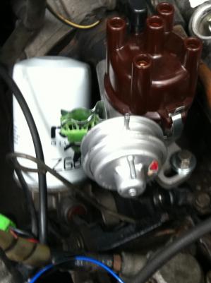
Alrighty well I had a bitch of a time doing this so I thought I'd put up a guide specifically for k engines. I've got an otherwise stock 4k-c engine in a 1980 ke55. before you start - i'd like to say that I'm pretty much re-writing a guide on toymods on this topic. I'd also like to point out that this I'm writing this for people like me who are new to the world of auto-electronics. If you're electrically minded you can probably skim over a lot of stuff here. If you ruin your engine or anything I take no responsibility... i don't know how you could do that, I'm just saying. There are other ways of doing this, such as finding a dizzy that suits that has an inbuilt ignitor, which may make things easier. I don't know about them as I've only done this once. I'm also writing this as a guide with these parts specifically because (at time of writing) all can still be bought brand new or reconditioned no problem. What do you need? * Basic tools * Basic wiring stuff - coloured wires, male/female spade terminals, few ring terminals, set of wire strippers/crimpers, electrical tape (I didn't do any soldering - just crimping... your call) * Bosch HEC716 coil * Bosch BIM024 ignitor module (referred to as 'module') * Electronic distributor to suit your k engine. I got one from Starlet with a 4k engine. * Gregorys manual with a wiring diagram helps but isnt necessary What does it cost? * Coil and module i got for $70 each new from repco. maybe cheaper on ebay, definitely cheaper from a wrecker if you don't mind second hand. Not sure of which cars will have them though * The distributor I got from ebay HERE. Those guys 'planetautoparts' are still selling them. They are completely reconditioned with all new parts. WIth shipping works out to about $100. Sometimes on sale for 40% off * All the wiring stuff including the crimpers was probably $20 from somewhere like Jaycar The distributor, coil and ignitor Let's start First, disconnect your battery. Then, make sure you understand your stock setup. Here's mine (before). Please note that I don't have a tacho. You can use this guide to install one I believe, but I haven't done so yet. Note the thicker black/yellow wire on the left. This is your +12v power This is a diagram of the stock setup Only two wires of the stock setup will be used. One is the +12v going into the left side of the ballast resistor (rectangular white thing). This is where you'll get your power. The other is the noise suppresor which is that little cylinder thing at the top of the bracket. it goes to the coil positive. It helps stop weird sounds coming through your radio Now here is a diagram of how we want everything to end up 1. Setting up the coil/module So pull out your coil and the ballast resistor. Disconnect the wires but make sure you know where they all went before hand (photos help). Now we wanna put the new coil and the module in. I discovered that it's damn easy to adapt the old coil's bracket to fit the new coil, and mount it in the same spot! Sweet! I just drilled a quick hole in the bracket to make it fit. I also needed a nice long thin bolt from the hardware shop to squeeze the bracket around the new coil. New coil, old bracket Ugly new hole drilled So stick that, with the noise suppresor back onto where the old coil was mounted. Next we need to mount the module. I drilled two little holes with a 5/32th drill bit in a fairly flat spot on the wheel arch area Note the module and the white goo behind it. The module comes with a sachet of white heat-sink paste. Jaycar also sells it in little tubes for a couple bucks, so i used a little extra. Smear that all over the back of the module before you mount it. This, and a good ground stop it from failing on you. This module get's it's ground from one of the bolt-holes that you mount it with... Sooo you could grind some deadener shit away from the underside of your wheel arch and have a the nut for that bolt up against bare metal... Instead of that I just ran a ring terminal from the front-side of the module's ground bolt to the bracket that the coil's mounted on. There's that done. 2. Getting the wiring sorted The wiring is annoying if you're like me and not electrically minded, but you'll get there in the end. Okay so here's a picture of my wiring all done... now keep in mind, I just grabbed the coloured wires from the hardware shop round the corner and they didnt have many colours... so basically nothing matches up to the colours on the diagram above. BUT it does work, and if you look at this picture and the diagram, you'll figure it all out. The high tension lead is disconnected for this pic obviously. Have a look at the module. * The black wire, and the red wire on the left two terminals (marked 3 and 7) go to the distributor. * The black wire from the right side terminal (marked 16) goes straight to the coil negative (this is the wire your tacho would have a cord going to). * The other terminal second from the right (marked 15) has the green wire. This wire goes to a spade terminal double adapter which then has a red wire to coil positive, and also plugs into the black/yellow +12v wire that's there from the stock setup. The coil positive also has the noise suppresor hooked to it. * also note the black cord from the module bolt going to the coil bracket. this is the ground All of the unused wires from the old setup should just be taped up and tucked outta the way. If I were doing an engine swap or something one day, I'll tidy all the wires and get rid of the unused ones. 3. Installing the Distributor Now we need to swap over to the new distributor... You can mark where the rotor currently is, but we're gonna check the timing later anyway, so I didnt bother. Unhook your spark plug leads, pop off the little vaccuum advance tubes (make note of which one went where, again photos help), unscrew the bolt holding the dizzy down and there should be just one black wire on the under side to unclip. Take out your old distributor and put it aside on some newspaper. IMPORTANT NOTE The rubber o-ring on the dizzy shaft needs to sit flush with the shaft body. At first I thought the dizzy was the wrong size and gave up. You must NOT be able to see the rubber o-ring once the dizzy is in properly, or it'll leak oil like a bitch. If your old o-ring is a bit haggard, order a new one FROM TOYOTA. The ones that don't fit properly are likely to be aftermarket. This picture is after I swapped them over. The clean dizzy is the new one with the old o-ring. The old dizzy has the aftermarket o-ring which isn't flush with the shaft I changed my plugs and leads at this point. You can drop the new dizzy in to make sure it fits, but we're gonna take it out again. Now we're gonna get cylinder #1 to TDC (Top dead center). This means that cylinder #1 will be at the peak of it's compression cycle. If the engine was running, at TDC cylinder 1 would be full of a compressed mix of petrol and air with a spark going off, about to shoot it back down. To get cylinder #1 to TDC, you take out the spark plug in cylinder #1 and put it aside. Grab a 19mm spanner and turn the engine over by the nut in the middle of the crankshaft pulley (car in neutral/park). With your other hand, stick your thumb in the hole where the spark plug was. As you turn the engine over (clockwise) after a short time you'll feel either a sucking feeling on your thumb (intake), or a blowing feeling (compression). As you feel it blowing on your thumb, look closely at the crankshaft pulley and you'll see a small notch on the inside edge next to the engine. On the engine is 3 marks - 20, 10, 0. You want the little notch on the pulley to line right up with the 0 mark on the engine. You need to make sure theres a distinct blow against your thumb. if not you've got that cylinder on the exhaust stroke, and need to turn it over again 360 degrees. With those 2 marks lined up on the compression stroke, you've now got cylinder #1 at TDC. Good job, put the spark plug back in. Now the goal is the line the distributor up so that the rotor is exactly on spark plug #1. Look down into the hole where the dizzy goes. At the bottom is a slot for the oil pump drive tang which is the part at the very bottom of your dizzy. This lines up with where the rotor at the top of the dizzy is pointing. Grab a long flathead screwdriver and get that slot lined up roughly to where the #1 mark on your distributor cap will be. Try to get it as close as you can. Now, with the dizzy out, get the rotor lined up roughly with the #1 point on the dizzy cap. Put the new dizzy in. You may need to turn it a bit one way or another a few times before it clicks right down into place. This part is like 'fine tuning'. With the bolt that holds the dizzy down screwed in but NOT TIGHT, you'll be able to move the dizzy around a bit with the rotor staying still. Get the rotor lined up with where the #1 point will be on the cap. You want it right on the dot. You might need to take the dizzy out again and adjust the oil pump drive slot again but you'll get it in the end. Once that's all lined up, carefully tighten the distributor hold down clamp bolt. Good job You can check your timing with a timing light if you or a friend has one later on. Otherwise my mechanic said he'll double check it for 6 coopers pale next time I drop in. In any case, if you've gotten TDC lined up with the rotor at spark plug #1, your engine will start. 4. Almost done At this point you only need to plug a few things in. * Plug the high tension lead from the coil into the middle of the dizzy cap. * Plug in all the spark plug leads to the dizzy cap. The order is 1-3-4-2. on the cap will be numbers or at least a number for #1. the rotor moves clockwise so just make sure they are in the right order or your car will misfire like a mofo * Plug in the two vaccuum advance tubes to the round guy on your new dizzy * Remember pins 3 and 7 on the module? They go to your distributor (the green connector on mine) IMPORTANT NOTE The colours of the two wires on my new dizzy were white and brown... not white and red. I assumed brown would = red, but the car wouldnt start. When swapped over it turned over straight away. Keep that in mind! That's it!! Reconnect your battery, double check all the wires/screws/bolts are nice and secure and fire it up. You can check your timing with a timing light if you or a friend has one. Otherwise my mechanic said he'll double check it for 6 coopers pale next time I drop in. Any problems at all, just post here and I'll do my best to answer them. :y: :y: :y: :y:


-

Aftermarket Digital Temp Gauge Step By Step
jackbyo replied to Evan G's topic in KExx Corolla Discussion
bumping an old thread here with some more info if anyone's interested. if you'd rather a needle point display that matches the stock gauges. (as towe mentioned above. it's as fast an accurate as a digital display as well) and you don't need to modify anything I picked up a 52mm VDO electric gauge which matches the stock ke3x-5x gauges perfectly. the good thing is that it's made to go with a VDO temp sender which fits in with a little adapter - no modifications required prices and part numbers are as follows gauge - 310010014 - $44 temp sender - 320.002 - $15 and whomever you buy it from should have a tapered brass adapter to bring the 1/8th thread size of the sender to M16x1.5. cost me $7 Oh yeah and another $8 will get you a tidy little VDO bracket to fit the gauge into so all up i paid less than $75 and installed it in an hour. same wiring Evan wrote up 1. Black - ground bolt anywhere 2. Red - power from a fuse (thanks evan) 3. Blue - sender. I taped the end of the wire to a coathanger and poked it through the rubber grommet on the firewall where the main wiring loom travels. easy as VDO makes good parts too... i wouldn't bother with Calibre shit from SCA as it's ugly, more expensive and made in China. here it is, I mounted mine under my choke with 2 pre-existing bolts. I gaffed those wires outta the way after this photo :y: now instead of worrying about a very old, incorrect mechanical gauge with no numbers on it, i now know that my engine is sitting just under 80 degrees in traffic on a hot day :cool: future plans are to take apart the dash cluster and mount this gauge were the now dead stock gauge lives :y: cheers
-
wow i love it, ive never seen one before either id be keen to buy if one pops up in sydney tho
-
mate you've got a great car there. looks like the rear panels aren't damaged which is the main thing, the boot, doors, fenders and bonnet can all be replaced. I would definitely consider welding in new metal on the wheel arches... I just sanded and bogged mine a few months ago and it's already creeping back... it's worth doing proper first time especially if you've got a mate who will do it. for wheels theres a few options... To me, nothing says rat rod like dirty stockies, but even better are jelly beans or 12 slotters. ive got performance challengers on my '80 coupe which i think look great, as do bathurst globes. I just got a petrol cap sent to me by a member called ke20rolla who had something going in the 'vehicles wrecking' section... check out that whole for sale section and you'll find good deals on rolla stuff. I'm fairly sure the petrol caps were the same for most rollas so you should be sweet. otherwise there are some aftermarket on ebay from thailand or somewhere i'm picking up some new seats this weekend so i'll be selling mine. They are in great condition, have a look in my ride thread in my sig even though the seats are the same for the 4 door, only the coupe seats fold forward so they can be hard to track down. reupholstering is another option but tends to be expensive i'll let you know when i put up the sale edit: just realised you're in melb. i'd be happy to ship to whomever if they sort it out prior... will let you know
-
this thread is a great read keep it up
-
UPDATE!!! Brand new ignition!!! Today I put in all new NGK spark plugs, bosch leads, ignitor, coil and wiring!! With a starlet 4k-e reconditioned electronic distributor from the states to top it all off! Most of that stuff is in a photo i took up there once i had it all hooked up and timed correctly the mighty 4k turned over first go. this was after many failed attempts and 3 sparks being shot up my arm :cool: It's actually starting instantly now instead of the starter motor pumping away for ~5 seconds like it was. so good. overall a really nice upgrade, and i bought all the parts brand new for about $110, with the rebuilt dizzy from the states for $60 or so. I followed a great guide over at toymods, but i may rewrite it specifically for the k engines :y: also notice i managed to modify the existing bracket for the stock coil to fit the new bosch coil :y: righto gonna go for a spin now. next step is interior... keep your eyes out for new black carpets/door cards and cream vinyl seats... mmmm Edit: If anyone's interested, my guide to installing an electronic ignition system is HERE :y:


-
was just reading over another thread and someone mentioned about when hand cranking to be in neutral.... ive got an auto and i've been doing some dizzy stuff today and was rotating it by hand from the pulley, but it was in park gear the whole time... it was a bitch to turn but I thought it was supposed to be like that or something... f@$k. have i screwed my 4k or anything bad? :ninja: :ninja:
-
ahhh i was confusing cylinder sequence with firing order... :y: Just had a look at my dizzy cap and it's got numbers which make it all line up to 1-3-4-2 cheers
-
pretty dumb question here but.... would #1 be the cylinder closest to the fan and number #2 be closest to the firewall? cheers
-
Hey so i'm installing a new electric dizzy in my 4k-c Pretty basic question I've got, Just say ive lined up spark plug number 1 at TDC, but the new dizzy timing is waayy off, do I adjust the oil drive tang slot (at the bottom of the dizzy hole) with a long flathead screwdriver to get the rotor to line up close, and then use the dizzy bracket and bolt to get it fine tuned?
-
all this applies to putting a k50 gearbox from a ke70 into a stock ke55 aswell right? and i read somewhere that i don't need to cut a new hole for the shifter as my ke55 is an auto... is that right also? thanks
-
any updates???
-
damn all those last images didnt work.... and I'm interested to see it because it looks like you've got the exact same model and the only other ke55 in the same colour/trim as mine! check in the sig hope to see some progress pics cheers
-
a year later... I'm hoping that this thing hasnt been left to rust... can't see the pics either. update?
-
My First Corolla, Is A Ke30. New To Forums Too :)
jackbyo replied to Finn.KE30's topic in Rollaclub Rides
keen to see some updates on this<br><br>also, with your carpet, was that brand new or did you dye it??<br><br>how are the painted door cards going aswell? does the black rub off?<br><br>cheers<br> -
anyone been lately?
-
i reckon you need to add some more photos
-
hah that's mad
-
Got the new distributor in, but not yet wired up the ignitor or module it turned out to be the rubber o-ring that was the culprit! I swapped them over and it dropped right in! i think I read in the wiki somewhere that someone said they always had to order these specific o-rings from toyota will update with pictures oh and just a quick one of a working temp gauge i mounted under the dash today (those wires were gaffed outta sight afterwards) stayed around 80 degrees when idling for 20 minutes on a hot day.... very good :y: :y:


